Tuesday, November 3, 2009

Portland Road Retail

Project: Portland Road Retail
Location: Salem, Oregon
222 Commercial Street, N.E.
Salem, Oregon
97301
General Contractor: N/A
Square footage: approx. 4,060 sq. ft.
Status: Completion Winter 2009


This is a small retail building located on Portland Road in Salem. It only had the capacity for two tenants and was originally designed for Subway Sandwiches. The roof open-web wood chord joist with metal webs. The sheathing was plywood and was supported on masonry walls. The masonry walls were also used to resist the lateral forces. Overall this was a fairly straight forward building and construction went effortlessly and fast.

Monday, September 14, 2009

TVF&R Fire Station 58 Boulton

Project: TVF&R Fire Station 58 Boulton
Location: West Linn, Oregon
Architect: Peck Smiley Ettlin Architects
4412 SW Corbett
Portland, Oregon
97239
General Contractor: CSI Construction
Square footage: approx. 8,391 sq. ft.
Status: Completed Winter 2010

This was another fire station for Tualatin Valley Fire and Rescue in the West Linn area. The style of station 59 in the Willamette area was to match the buildings in the surrounding area. Station 58 on the other hand is located in a residential area and was not strict as station 59. Although the community was allowed input to the final design.

It was a 2-story structure and all wood construction. The second floor foot print is 9 feet smaller all around than the floor below. The walls for the second are supported on glulam beams which are then supported on columns down to the foundation. There is a beam line that runs north/south at the roof to support pre-manufactured press-plate trusses. The trusses were a mansard style and it created a well area for mechanical units to be placed and a solar panel on the roof. They also mounted a radio antena in this area. The east side the roof extended to the building edge below as to create a patio on the second floor.

Lateral forces from the roof diaphragm were taken out through shear walls on the second floor and transferred through drag struts and the second floor diaphragm. Beams/columns were sized to resist the lateral forces.

Most of the second floor framing used glulam beams. Over the apparatus bay steel wide flange beams were used which were supported on HSS columns to the foundation. The depth and cost of using glulam beams in this area got too deep and costly and they required as much clear height as possible to service the trucks and other equipment.

Because the project was built on a slight hill, extensive retaining walls were required to level the project site. A portion of the retaining wall system was not only designed for the soil pressure, but also the load from the trucks, as the drive way curved into the building. The construction took considerable time and in the end came out looking nice. A portion of them allowed for a planter near the street level.

Both this station and Station 59 replace existing stations. The capacity nearly doubled for Station 58 compared to the previous station.


In addition to Station 58 and 59, our office did Station 34 and Station 53 an several others.

Thursday, September 3, 2009

TVF&R Fire Station 59

Location: Willamette Falls/West Linn, Oregon
Architect: Peck Smiley Ettlin Architects
4412 SW Corbett
Portland, Oregon
97239
General Contractor: CSI Construction.
Square footage: approx. 7,013 sq. ft.
Status: Completion Fall 2009


The fire station is a 2-story all wood construction. The only exception is where wood beams were unable to adequately span with the required load and clearance requirements. Steel wide flange beams were used in these cases with wood nailers fastened to the top flange with carriage bolts. Open web wood joist were used to span over the apparatus bay and repeated in the roof at the same location to minimize additional loads to the second floor joist. The remainder of the floor and roof framing was accomplished by using plywood web joist.

The foot print of the second floor was smaller than the first floor, creating an offset above. A steel angle was bolted to the studs to carry the brick on the upper wall. Many of the windows around the building had curved lintels. Steel HSS jambs and HSS headers were used to acheive this.
The construction of this building went fairly smooth, with the usual twist and turns. Head clearance at the main stair became an issue and we had to modify the frame that was already in place. The stair at the back needed an additional support, so a rod was added and supported off the glulam beam above.

In addition to Station 58 and 59, our office did Station 34 and Station 53 an several others.

Wednesday, August 19, 2009

Brookings Medical Center

Project: Brookings Medical Center
Location: Brookings, Oregon
333 NW Fifth Avenue
Portland, Oregon
97209
General Contractor:TODD Construction
Square footage: approx. 33,500 sq. ft.
Status: Completion February 2011
Brookings Medical Center which is part of the Curry General Hospital Health Network is a new facility in Brookings, Oregon.
The roof framing consist of light-gage metal joist which is sheathed with Fortacrete Structural Panels. The joist were supported by wide flange steel beams with the exception of glue-laminated beams longitudinally along the front wall because they were exposed to the lobby below. Essentially there are three different zones with the roof. On the left side was a sloping roof with a 1:12 slope towards the center. On the right side, we had a similar condition but the roof slope was 2:12. The center portion was dropped down by about three feet. In that center bay there was a penthouse for mechanical grilles.

The steel beams were supported on steel HSS columns and for the most part hidden in many of the walls. Non of the walls were used as bearing walls due to potential tenant improvements later in the building construction. However some of the walls became dedicated shear walls which attached to the roof structure.

The floor consist of steel beam framing with concrete slab on metal decking. This was about 67% of the floor area, while the remaining 33% was slab on grade. The retaining walls were formed with ICF (Insulated Concrete Forms) as well as the exterior concrete non-retaining walls.

The lateral resistance on the front main entry was taken through a series of rod bracing at the mid-height and then through the column to the foundation. The architect took the opportunity to dress the connection up and developed a visually pleasing connection. Also the glue laminated beam connections at the top have been dressed up as well.

The entry canopy consist of metal decking over steel HSS beams that cantilevered beyond the steel wide flange support beam. The HSS beams were hung from the steel beam to give it that pass under look. The steel wide flange beam is supported with a steel HSS column in the center and concrete piers on the ends.

Carlton Fire Station

Project: Carlton Fire Station
Location: Carlton, Oregon
Architect: Ivars Lazdins
3004 SW Bennington Drive
Portland, Oregon
97205
General Contractor: Haworth Construction
Square footage: approx. 7,300 sq. ft.
Status: Completed Summer 2009


Carlton Fire Station was two different building types. The apparatus bay was fabricated from a pre-engineered metal building and the administration/kitchen/training was constructed with wood framing. The two buildings were separated with seismic joint so they could act independently during a seismic event. The only engineering we did on the apparatus bay was the foundation and mezzanine in the apparatus bays. Originally it was to be designed as a five bay station, but budget cuts reduced it to a four bay station with only one mezzanine.

The mezzanine was design as a self-supporting structure as well, taking all vertical and lateral loads independent of the metal building structure. The structure was plywood floor sheathing on I-joist framing to 2x wood studs and plywood shear walls. Because it was a wood structure and it was small enough, it tied into the main wood building. Therefore, it shared a shear wall.

It was a fairly conventional wood structure, with press-plate wood trusses in the roof and 2x wood studs with plywood sheathed shear walls. Because of that, the building itself presented very little field construction issues.

NCSD Oregon Trail Elementary School Additions

Project: Oregon Trail Elementary School Additions
Location: Clackamas, Oregon
Architect: Architects Barrentine Bates Lee, AIA
200 North State Street
Lake Oswego, Oregon 97034
General Contractor: Bourke Construction.
Square footage: Conference Room: 545 sq. ft. / Cafeteria Addition: 1,160 sq. ft.
Status: Completed Summer 2009


This was an addition of two new spaces to an existing elementary school. The first one was a new conference room that was added next to the main entry. It consisted of plywood web I-joist with plywood roof sheathing for the roof and plywood shear walls on wood studs. As with any remodel it is the interface of the existing structure to the new that tends to complicate a project. This one room went up without an issue regardless of the existing connections.

The cafeteria portion was added to the east side of the existing cafeteria, providing more space for the kids at lunch time. The interface on the south did not present any problems, but it was the connecting of the new structure with the existing east wall. The existing wall was framed with large glue laminated beams (8 3/4 x 21) that were supported on 8 inch square tube columns. Below the beams were a series of smaller window openings jambs to resist wind. The architect/school wanted to remove the two end columns and hide new ones in the new walls, keeping the existing center column in place. This would provide a more open space than it would have if all the columns remained. I stitched bolted a pair of steel channels (C15x40) on either side of the existing glulam beams to increase the span to the new walls. Special connections were detailed to pick up the ends of the glulams where the columns were removed.

One major issue that presented itself on the project was the west wall of the new storage room. When demolishing the wall the contractor discovered an existing drain pipe in the location where the new column was to be placed. So they relocated the column and changed some of the framing around the area. We had to reframe the wall with new LSL studs where the TJI studs were removed. The architect lost 6" of space in the storage room as a result.

Tuesday, April 28, 2009

Newport Head Start

Project: Newport Head Start
Location: Newport, Oregon
363 State Street
Salem, Oregon 97301-3533
General Contractor: Greenberry Construction.
Square footage: 4,050 sq. ft.
Status: Completed 2009

An old mechanical repair shop that was converted to a Head Start building. The original building was constructed with CMU (concrete masonry units) on three sides and the front had concrete frames. We were able to secure the 1953 existing drawings for this building and the 1995 remodel so we could evaluate the building for current code standards.
May 28th was the grand opening for the center and was awarded for its "green" use.
The existing concrete structure appeared to be adequate for new lateral loads as did the masonry walls. However, there was no account for out-of-plane loading to the walls. They were already furring out the inside of the wall, so we opted to run the metal studs up to the underside of the existing roof diaphragm. These studs were fastened to the masonry walls with metal clips every 24 inches and screwed into the roof sheathing. New plywood was added to the roof of the existing structure to give it better diaphragm capabilities.

The new portion of the facility was standard wood framed construction consisting of press-plat trusses tying into the existing roof where applicable. The walls were 2x wood studs with plywood sheathing and lateral connections for wind/seismic forces. On the east side, a covered area was added which housed new mechanical units. It was framed with 2x rafters, glulam beams and wood I-joist. Lateral resistance was taken out by HSS columns embedded in nonconstrained footings on the outer perimeter.

NCSD Administration Building

Project: NCSD Administration Building
Location: North Clackamas School District
Architect: Barrentine Bates Lee, AIA
                    200 North State Street
                    Lake Oswego, Oregon 97034
General Contractor: NA
Square footage: 22,500 sq. ft.
Status: Cancelled 2008.

This project was at the 95% complete level at the time it was cancelled. Some of the cancellation was budgetary matters and neighborhood input.

This project was a 2-story office building for the school district's administration department. It was a steel construction roof and composite floor along with 12 inch thick tilt-up panels to resist lateral loads. The layout was, for the most part, symmetrical, which made the design fairly straight forward. For the floor, steel-concrete composite girders ran in the east-west direction and smaller steel-concrete composite joist in the north-south direction. The roof had steel joist and girders which matched the oreintaion of the floor framing. On the roof, on either side of the entry core, were mechanical units for the building. They sat on concrete pads to help reduce noise levels.

The shape of the building was rectangular with the entry on the east side of the longitudinal face. It was partially open to the roof above providing a spacious entry. They wanted to avoid moment frames, to keep the cost down so concrete tilt-up panels were designed to act as a resisting element. The architect wanted the corners exposed, meaning they wanted glass store fronts at every corner. They also did not want columns to be seen. So the steel beams cantilevered from the inside face of the tilt-up panels. These 12" thick panels were attached to the steel framing and the steel framing acted as a drag strut. The most difficult portion of this building was the connection of the panels to the steel framing.

Monday, April 27, 2009

Lebanon Fire Station 34


Project: Lebanon Fire Station 34
Location: Lebanon, Oregon
4412 SW Corbett
Portland, Oregon 97239
General Contractor: NA
Square footage: 9,700 sq. ft.
Status: Completed 2008.


This fire station had two different lives. The first life it lived was as a rigid frame metal building with wood modifications. The larger spanning rigid frames are over the apparatus bay and the smaller frames in the kitchen/dorm/meeting area. Shed frames cover the utility areas. The down side with this design was the specialty framing around the meeting room. Having worked for a metal building company years ago, there is major complications when modifications are made to the standard structure.

Once the contractor was awarded the project, they suggested making the station out of wood framing. There was a major cost savings with this new design. Therefore we revised our calculations to accommodate the changes. We had 80 foot long press plate trusses spanning over the apparatus bay and living area. In hind sight, 80 foot long trusses tend to be more difficult to erect, but after consulting the contractor, we proceeded forward with these trusses.

Overall, this was a straight forward wood construction building.

Wednesday, April 22, 2009

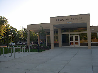
NCSD Linwood Elementary School Remodel

Project: Linwood Elementary School Remodel
Location: North Clackamas School District
Architect: Barrentine Bates Lee, AIA
200 North State Street
Lake Oswego, Oregon 97034
General Contractor : P & C Construction
Square footage: 19,000 sq. ft.
Status: Completed 2009.


This was an existing elementary school that added a new classroom section, a new media area, new gymnasium and expanded office and entry. It also included some hall and covered play shelter modifications.

The new media center was added to the northwest end of the classroom wing, providing a 4800 square foot area to work with. Most of the framing was wood web joist supported on bearing walls, with the exception of the middle section. Because of the diagonal exterior wall, steel wide flange beams were used to support joist. The detail through the steel beam calls for flange width nailers attached to the top. On one of the beams, a 4x member was fastened down but not cut to width. This meant that the nailer was overhanging and is not widely accepted. Because the overhang was just under 1/2", no modifications were made.

The gymnasium went through two designs on our part. The first was to create square columns at the corners and at each girder location. Then a spandrel was to be installed between at the roof level, then a window and 7.25" panels below the window. The end walls were just 7.25" tilt-up panels. When bid time came and the project was awarded to a contractor, they proposed some cost savings to the school district. It was to eliminate the cost construction for conventional tilt-up walls. Although I was proud of some of the connections on the spandrels, I had always wondered how they might build this gymnasium with all the required pieces. On the east end of the building, the roof line dropped with the exception of the middle mechanical room. This was my first concrete tilt-up project ever, so there was a little learning curve. I also used a program to design the walls rather than by hand, so that I might get a better handle of the design process. It was a module within the RAM Advanse program.

The entry was enlarged and added covered entries. Because the entire addition was all storefront, this provided no lateral resistance. Around the perimeter they had 18" square columns, that were used to resist lateral loads. Glue laminated beams were used as drag struts and fastened to the concrete columns. Some modifications were also provided to the existing structure to make it a little more laterally secure.


Some minor modifications were done in the covered play area in the north wing. One of the columns in the southeast corner had severely rusted out at the base and we replaced it with a new section of steel tube.

The final addition was in the north wing as well. It was going to be an alternate, but in the end it became part of the project. It mimicked the existing classroom floor plan that it was attaching to, so the design was fairly simple. It had 8 foot cantilever roof joist that created some special detailing. Overall it was a fairly simple addition design wise.

Monday, April 13, 2009

Broadway Town Square


Project: Broadway Town Square
Location: Salem, Oregon
363 State Street
Salem, Oregon 97301-3533
General Contractor: Sharpcor, Inc.
Square footage: 200,000,000 sq. ft.
Status: Completed 2009.

My fourth project that I worked on with Chris. It was a 4-story apartment complex with retail on the ground floor and a movie cinema on the north end, which Chris worked on. The cinema is a tilt-up and steel construction and the apartments is a steel construction on the first floor and wood construction to the roof.

The first floor framing consist of open web floor joist with wide flange girders with a concrete on metal decking. It was not designed as a composite floor system. The east and west side had moment frames only because of the store front system. The lateral system in the other direction was braced frames. Above that, the framing system was wood floor joist with plywood shear walls. Brick veneer covered the face of the building up to the third floor. The apartment decks were a concrete slab that cantilevered off a pair of HSS beams. The cinema was tied to the apartments with a bridge at the third floor.
Early on in the project, it was discovered that a large tank was buried under the soil while preparing the foundations. This was located just south of the elevator. Several options were suggested by the soils engineer, but in the end they settled on helical anchors under all the footings within a 56 foot wide area. At the other end, combination footings were utilized due to property line issues which ended up working well.

Thursday, April 9, 2009

Crooked River Fire Station

Project: Crooked River Ranch Fire Station
Location: Terrebonne, Oregon
Architect: Ivars Lazdins
              3004 SW Bennington Drive
              Portland, Oregon 97205
General Contractor: NA
Square footage: approx. 9000 sq. ft.
Status: Completed 2008

My second project and it was all wood construction with the exception of a CMU wall at the end of the apparatus bay. The apparatus bay was nearly 80 feet wide and used press plate trusses to frame the roof. We broke up the span by a line of glulam beams and some columns to break up the spans. Trying to use press plate trusses with 80 foot spans can be difficult to erect. As can be seen in the picture, solar panels were added to the roof and according to the architect, this worked out really well.

The lateral system was mostly plywood shear walls with the exception of CMU in the front and back of the apparatus room. As mentioned, the exterior end wall was also CMU up to the plate line.

We had to work through the detail of the seismic joint between the main building and the apparatus building. The maximum gap ended up being 3 1/2 inches at the roof peak. They also installed heating coils in the floor slab which was heated by the solar panels above.

Wednesday, April 8, 2009

Salem Senior Center

Project: Salem Senior Center
Location: Salem, Oregon
4412 SW Corbett
Portland, Oregon
97239
General Contractor: Todd Construction
Square footage: 32,000 sq. ft.
Status: Completed 2008.

The Salem Senior Center was my third project I worked on since I joined Lewis and Van Vleet. It was new a 2-story senior center located near downtown Salem, to the north.

The building is constructed primarily of steel. The roof originally was constructed with open-web wood chord/metal web joist with plywood sheathing. But after some number crunching by the architect and developer, they opted to use open-web steel joist with metal roof decking. Centered in the roof is a clerestory to provide light below.
The second floor was framed with a series of wide flange beams framing into wide flange girders with a composite floor diaphragm. The configuration of the building was such that the upper floor plan was square in nature and the lower floor more rectangular, in that a portion extended out beyond. This provide a location for mechanical units and the same sort of framing was extended to that area. It allowed to surface to be concrete as well, providing some damping below.

On the first floor plan, they had a great hall, but the wall from the second floor rest about in the center of the hall. The architect and owner did not want a column in the center of the hall, so we designed a plate girder to span the length of the hall, nearly 64 feet. The flange width needed to be 10 inches maximum 2 1/2 inches thick. The depth was kept at 60 inches with a 1/2 inch thick web, to avoid interference with the window system. At one point, we suggested a truss fabricated of HSS sections, but it was too difficult to coordinate windows around web openings.

The lateral system was a series of moment frames with two braced frames. In the end, it turned out to be all moment frames because of openings and such required by the architect/owner. They were designed as special moment frames in accordance to AISC standards and utilized the "dog bone" style connection.

Initially I started the design using RAM Structural System. I had never used this program so it was a learning experience for me. I did not have enough time to really assuage the troubles I was having with designing the moment frames within this program. After discussing it with Lance, I opted to use RAM Structural System to design only the composite gravity loads and then did the moment frames in RISA 3D. This worked well in the end.

The building turned out to be a real nice addition to the community. I had stopped by one Sunday when they were having a wood carving fair. I engaged one of the men there about the place and told him I was the structural engineer on the project. He then informed me, the only real complaint was that the janitorial room was 3/4's smaller than over at the other building.