Showing posts with label Steel. Show all posts

Monday, December 13, 2010

Progress Ridge Town Square

Project: Progress Ridge Town Square
Location: Beaverton, Oregon
Architect: Ankrom Mosian Architecture
6720 SW Macadam
Portland, Oregon
97219
General Contractor: Robertson & Olson Construction, Inc.
Square footage: As noted in blog below
Status: To Be Completed Spring 2011
This project is being developed by Gramor Development and is to be completed approximately in the spring of 2011. The overall project size will provide 200,000 square feet of various retail and entertainment. It is being built between the cities of Tigard and Beaverton and is near the neighborhoods of Murray Hill and Bull Mountain. New Seasons grocery and Cinetopia will occupy the larger buildings with several retailers surrounding these businesses.

Cinetopia was designed by another office and Lewis and Van Vleet, Inc. designed the buildings AK, B-F and HJ in conjunction with Ankrom Mosian Architecture. My responsibilities were for buildings B through F and they will be covered here in this blog. The other buildings were designed by two other engineers in our office and are being constructed at the same time and will not be mentioned at this time. Also the construction phase is currently under way and will be updated as it proceeds.

Building B - 7,724 square feet.
Building C - 6,712 square feet.
Building D - 6,072 square feet.
Building E - 6,314 square feet.
Building F - 7,139 square feet.

Building B
This building is 49 feet wide by 158 feet long and has a roof height of approximately 20 feet. The roof diaphragm consist of plywood sheathing over plywood web I-joist and has a blocked diaphragm at each end. Down the longitudinal length of the building runs a series of glue-laminated beams of which the I-joist hang from. A mechanical also runs down the longitudinal center, 10 feet on either side of the grid centerline. This allows the mechanical engineer to place a unit at any location within that zone. A wood ledger is fastened to the metal studs for the joist to hang from and allows the studs to cantilever upwards for the parapet. The lateral loads were taken out in the longitudinal direction with short plywood shear panels on metal studs. In the transverse direction, the lateral forces were transferred into masonry wall piers.

Several styles of canopies were used around this building to match the style of the storefront. One is constructed of 10 inch channels and diagonal rods supporting them. Another series is perpendicular glulam beams supported again with diagonal rods. Both are covered with metal decking. On the west end of the building are a perpendicular beams and diagonal braces that are supporting metal deck on glulam beams running parallel with the building face. They requested to use Alaskan Cedar glulams.


Building C
This is a 49 foot wide building by 150 foot long building with the same roof height as building B. The construction of the building and some of the canopies is the same as building B. The only exception is the false tower located in the southeast corner of the building. On the east face of the building, the masonry extend to a level approximately 6 feet above the top of the main building parapet. The remainder of the height is framed with HSS columns and beams. On the south face it is framed with HSS columns and beams and no masonry piers. Storefront glass extends to a foot past the roof line and the remainder is siding. For appearances, the "look" is wrapped around over the roof and supported by a steel structure and covered in wood siding. A wood trellis wraps around the south and east face and dies on the roof zone

Building D
Width of this building is also 49 feet and is 121 feet long with the same roof elevation. This building is the same as building C other than mirrored and rotated. It has the same false tower as well.

Building E
This building has a completely different foot print than the other three previous buildings. The main width is 56 feet and the maximum length is 99 feet. Again the roof height is the same as the previous buildings.The northeast half of the building is diagonal slightly and has a tall tower entry. Originally this tower had a large canopy that fastened to the sides. The project architect at that time wanted this canopy to be movable so that it would be in the upward position to let sunlight in in the morning and block it in the evening. The structure for this canopy was designed and awaited the mechanical portion to be design. The canopy was 27 feet wide and cantilevered approximately 15 feet out. It was constructed of tapered wide flange beams with 2x6 joist spaced at 24 inches on center spanning between the tapered beams. A few months into the start of the project, this canopy was scraped and the tower was redesigned. The foot print of the tower became longer and narrower and the front was a grid work of 12 inch deep wide flange beams. Smaller canopies were used and the concept of a moving canopy abandoned. Many of the other features of this building mirror what has been designed on the three previous buildings.


Building F
Like building E, building F is a completely different design. For the most part it resembles buildings B-D with the exception of the northwest end of the building. At that end of the building there is a covered area and a portion of the shops utilize glass overhead doors. Originally this was designed with I-joist on the interior portion and 2x members for the exterior. Since then Alaskan Cedar glulam beams have been used to replace the I-joist and 2x joist. The glulams are spaced at 48 inches on center, roughly and 2x T & G spans between the beams.

Monday, December 6, 2010

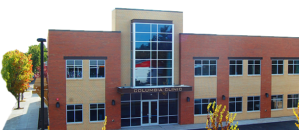
Columbia Clinic

Project: Columbia Clinic
Location: Portland, Oregon
Architect: Tuan Q. Luu Architect
7426 SW 54th
Portland, Oregon
97219
General Contractor: Perlo Construction
Square footage: approx. 5,500 sq. ft. 1st Floor/ 5,220 sq. ft. 2nd Floor
Status: Completed Fall 2010

A two story building located in southeast Portland on 82nd Avenue near SE Powell Blvd. The majority of the construct consist of open-web steel joists and steel girders and columns. The roof was metal decking and the floor was metal decking with a concrete slab. One large HVAC unit was placed on the roof instead of several smaller units. To reduced noise and vibration the unit was placed over a concrete tub.


The lateral system was all supported by masonry walls. The south side of the building was in the property line therefore the footings could not extend beyond the wall. The beam line which supported the joist ran parallel to the south wall and was not centered with the width of the building. Therefore a combined footing was used to support a grade beam which supported the masonry wall and the column loads inside. The west wall was also all masonry with the exception window and door openings and was not on the property line.
The north wall of the building was laterally supported with masonry piers. The areas between the masonry piers were infilled with steel beams and metal studs. The east exterior was not supported laterally in that a masonry wall was built at the stair well and the diaphragm was cantilevered off that wall

The construction phase went smoothly with the exception of a small blow out on a masonry pier. Design and fabrication wise, the entry portion of the building was the most complex feature. Large 24 inch deep steel beams supported the floor edge and steel tubes were sliced and fitted on the wide flange beams to cantilever out to pick up the canopy and fake glass tower. In the end it came out rather appealing.

Check out their website: www.columbiaclinic.com/

Wednesday, August 19, 2009

Brookings Medical Center

Project: Brookings Medical Center
Location: Brookings, Oregon
333 NW Fifth Avenue
Portland, Oregon
97209
General Contractor:TODD Construction
Square footage: approx. 33,500 sq. ft.
Status: Completion February 2011
Brookings Medical Center which is part of the Curry General Hospital Health Network is a new facility in Brookings, Oregon.
The roof framing consist of light-gage metal joist which is sheathed with Fortacrete Structural Panels. The joist were supported by wide flange steel beams with the exception of glue-laminated beams longitudinally along the front wall because they were exposed to the lobby below. Essentially there are three different zones with the roof. On the left side was a sloping roof with a 1:12 slope towards the center. On the right side, we had a similar condition but the roof slope was 2:12. The center portion was dropped down by about three feet. In that center bay there was a penthouse for mechanical grilles.

The steel beams were supported on steel HSS columns and for the most part hidden in many of the walls. Non of the walls were used as bearing walls due to potential tenant improvements later in the building construction. However some of the walls became dedicated shear walls which attached to the roof structure.

The floor consist of steel beam framing with concrete slab on metal decking. This was about 67% of the floor area, while the remaining 33% was slab on grade. The retaining walls were formed with ICF (Insulated Concrete Forms) as well as the exterior concrete non-retaining walls.

The lateral resistance on the front main entry was taken through a series of rod bracing at the mid-height and then through the column to the foundation. The architect took the opportunity to dress the connection up and developed a visually pleasing connection. Also the glue laminated beam connections at the top have been dressed up as well.

The entry canopy consist of metal decking over steel HSS beams that cantilevered beyond the steel wide flange support beam. The HSS beams were hung from the steel beam to give it that pass under look. The steel wide flange beam is supported with a steel HSS column in the center and concrete piers on the ends.

Tuesday, April 28, 2009

NCSD Administration Building

Project: NCSD Administration Building
Location: North Clackamas School District
Architect: Barrentine Bates Lee, AIA
                    200 North State Street
                    Lake Oswego, Oregon 97034
General Contractor: NA
Square footage: 22,500 sq. ft.
Status: Cancelled 2008.

This project was at the 95% complete level at the time it was cancelled. Some of the cancellation was budgetary matters and neighborhood input.

This project was a 2-story office building for the school district's administration department. It was a steel construction roof and composite floor along with 12 inch thick tilt-up panels to resist lateral loads. The layout was, for the most part, symmetrical, which made the design fairly straight forward. For the floor, steel-concrete composite girders ran in the east-west direction and smaller steel-concrete composite joist in the north-south direction. The roof had steel joist and girders which matched the oreintaion of the floor framing. On the roof, on either side of the entry core, were mechanical units for the building. They sat on concrete pads to help reduce noise levels.

The shape of the building was rectangular with the entry on the east side of the longitudinal face. It was partially open to the roof above providing a spacious entry. They wanted to avoid moment frames, to keep the cost down so concrete tilt-up panels were designed to act as a resisting element. The architect wanted the corners exposed, meaning they wanted glass store fronts at every corner. They also did not want columns to be seen. So the steel beams cantilevered from the inside face of the tilt-up panels. These 12" thick panels were attached to the steel framing and the steel framing acted as a drag strut. The most difficult portion of this building was the connection of the panels to the steel framing.

Monday, April 13, 2009

Broadway Town Square


Project: Broadway Town Square
Location: Salem, Oregon
363 State Street
Salem, Oregon 97301-3533
General Contractor: Sharpcor, Inc.
Square footage: 200,000,000 sq. ft.
Status: Completed 2009.

My fourth project that I worked on with Chris. It was a 4-story apartment complex with retail on the ground floor and a movie cinema on the north end, which Chris worked on. The cinema is a tilt-up and steel construction and the apartments is a steel construction on the first floor and wood construction to the roof.

The first floor framing consist of open web floor joist with wide flange girders with a concrete on metal decking. It was not designed as a composite floor system. The east and west side had moment frames only because of the store front system. The lateral system in the other direction was braced frames. Above that, the framing system was wood floor joist with plywood shear walls. Brick veneer covered the face of the building up to the third floor. The apartment decks were a concrete slab that cantilevered off a pair of HSS beams. The cinema was tied to the apartments with a bridge at the third floor.
Early on in the project, it was discovered that a large tank was buried under the soil while preparing the foundations. This was located just south of the elevator. Several options were suggested by the soils engineer, but in the end they settled on helical anchors under all the footings within a 56 foot wide area. At the other end, combination footings were utilized due to property line issues which ended up working well.

Wednesday, April 8, 2009

Salem Senior Center

Project: Salem Senior Center
Location: Salem, Oregon
4412 SW Corbett
Portland, Oregon
97239
General Contractor: Todd Construction
Square footage: 32,000 sq. ft.
Status: Completed 2008.

The Salem Senior Center was my third project I worked on since I joined Lewis and Van Vleet. It was new a 2-story senior center located near downtown Salem, to the north.

The building is constructed primarily of steel. The roof originally was constructed with open-web wood chord/metal web joist with plywood sheathing. But after some number crunching by the architect and developer, they opted to use open-web steel joist with metal roof decking. Centered in the roof is a clerestory to provide light below.
The second floor was framed with a series of wide flange beams framing into wide flange girders with a composite floor diaphragm. The configuration of the building was such that the upper floor plan was square in nature and the lower floor more rectangular, in that a portion extended out beyond. This provide a location for mechanical units and the same sort of framing was extended to that area. It allowed to surface to be concrete as well, providing some damping below.

On the first floor plan, they had a great hall, but the wall from the second floor rest about in the center of the hall. The architect and owner did not want a column in the center of the hall, so we designed a plate girder to span the length of the hall, nearly 64 feet. The flange width needed to be 10 inches maximum 2 1/2 inches thick. The depth was kept at 60 inches with a 1/2 inch thick web, to avoid interference with the window system. At one point, we suggested a truss fabricated of HSS sections, but it was too difficult to coordinate windows around web openings.

The lateral system was a series of moment frames with two braced frames. In the end, it turned out to be all moment frames because of openings and such required by the architect/owner. They were designed as special moment frames in accordance to AISC standards and utilized the "dog bone" style connection.

Initially I started the design using RAM Structural System. I had never used this program so it was a learning experience for me. I did not have enough time to really assuage the troubles I was having with designing the moment frames within this program. After discussing it with Lance, I opted to use RAM Structural System to design only the composite gravity loads and then did the moment frames in RISA 3D. This worked well in the end.

The building turned out to be a real nice addition to the community. I had stopped by one Sunday when they were having a wood carving fair. I engaged one of the men there about the place and told him I was the structural engineer on the project. He then informed me, the only real complaint was that the janitorial room was 3/4's smaller than over at the other building.